Monday, January 30, 2017

Week 2

      This week was the first time we had a Monday class meeting for capstone. We confirmed our budget with Dr. Gordon (it is $600) and updated him on the progress of our project. Max Murphy worked on Arduino code for the motor while the rest of the team went to Josh Park's office and created a 3D scan of the foot. This will be used to 3D print a foot/ankle "brace" that fits onto Isaac's leg.
Josh Park holding the 3D scanner to scan Isaac's foot.
It was found that wearing a sock made it difficult to complete and align the different scans, so the process was redone. The colored dots helped with alignment. 

An example of the 3D scan rendering.

This was the completed scan, which Josh sent us later in the week as an .STL file.
    Later in the week, we went to the shop again and constructed a new bracket for testing the motor. We also constructed a "shield" that will help stop anything that flies off during testing (if something should fly off). The force transducer is able to screw onto the side of the bracket, which will hopefully allow us to accurately measure the forces generated.

A sheet of metal was bent to fit over a 2x4 piece of wood. The motor will be mounted to the sheet metal.
Another view of the set-up. The motor is now mounted so that it will spin horizontally, rather than vertically.


The force transducer can be attached directly to the test bracket.

This is an example of how the set-up would be used during testing. The "shield" is open at the top as the weight would be unlikely to fly out of the top if the screw were to break. This also allows us to use the tachometer while the motor is running.
     We attempted to test out the motor; however, the screw we were using hit the side of the shield and broke. We placed an order with Dr. Gordon for a brass plate from McMaster-Carr. Once the brass arrives, we would like to go to the shop and mill out the following object.

The object we plan to mill out of the stock brass piece.
This object combines both the "arm" and the "weight" portion, so that we will no longer have to use a small M3 screw and mass. This should make the system much stronger and less prone to breaking/shearing off. The round end with holes in it is where the system will mount to the motor. Brass was chosen because it has a high density and is also able to be machined with our equipment. We are hoping to receive the brass early on during Week 4 and be able to mill out our shape, as most of our testing is at a stand-still until this step occurs.
     We also continued to work on the Arduino code that controls the motor, and also started discussing how we plan to attach the elastic bands to the harness. As of right now, we are planning on sewing the elastic bands; we will fold the elastic band over itself to create a loop. This loop would then allow the ban to be taken off the harness if need be. This will likely be delayed until further in the semester, however, as testing the motor is our number one priority for the time being.


Monday, January 23, 2017

Week 1(?); First Post of Second Semester

     This is the first week of class since Christmas break. Over break, we ordered parts for our project, which were waiting when school resumed. Below is a picture of the items we ordered.

The items ordered over Christmas break.

     We double checked that we received all of the items, and then started constructing the base plate in order to test the motor. We went to Wes' shop and got his help to do this. We bent a sheet of aluminum to create a 90-degree bend, and also punched holes into the metal in order to anchor the motor to the plate.


The above pictures show our team fabricating the test bracket in the lab.
     Once the test bracket was constructed, we began our motor testing. We started out by using a 50 mm screw and spinning it by itself at different speeds (increased incrementally). We then added a small mass and repeated the process, and slowly worked up to larger masses. The mass sets were threaded onto the screw via the hole in their centers. We used the tachometer to measure the RPM of each different combination. The motor was spun via an Arduino and motor controller (as shown on the order form), with much of the code being found/written by Max.
This shows the set-up with one of the smaller masses being attached to the motor.
The motor test bracket as shown from the back (held down by a clamp).

Using the tachometer to measure the RPM of the spinning mass. 
Max used Arduino code and a motor controller to control the motor's speed. 
The results from the testing can be seen in the picture below:

The "scary" sections were when the motor hit a harmonic and vibrated in a scary-fashion, which didn't allow for proper readings.
     We also met up to discuss our options for mounting the mass to the motor, as well as the motor system to the ankle. During our testing, we had found that the head of the 50 mm screw sheared off, launching the mass into the air. Obviously we do not want this, so we explored several alternative options for attaching the weights to the motor safely. Some ideas were using a bigger screw, welding a screw/rod to the motor, redoing the bracket to change the resonant frequencies, using a bike cable rather than screw, and machining out a solid piece that would serve as both the mass and the "arm." We felt that the last two ideas were the best, but we think that there will be difficulties with both options. Therefore, we are hoping to discuss them with our tech adviser and/or Wes before purchasing anything.

Ideas of how to attach the mass and motor configuration together. 
     For attaching the motor to the ankle/leg, we want something that is cost-effective (re: not expensive), but that also provides stability. Our current ankle brace would not be sufficient on its own as it would allow a lot of room for movement once the motor started spinning. Ideas we contemplated were 3D printing "shin guards" and then Velcro cinching them down, buying a sturdy boot (such as a ski boot or work boot), or purchasing a sturdier ankle brace. We believe we will try to 3D print material, as this would not count against our budget. However, we would again like to consult with both the tech adviser and Josh Park before making a decision.
Ideas of how to attach the motor configuration to the ankle. 

Monday, December 5, 2016

Week 11

     This week we finalized our design for the motor module, as Deliverable 5 and the final presentation/packet were due at the beginning of Week 12 (December 5). We had officially decided on using an off-centered mass spun by a motor, and during class we discussed different placement options (i.e., at the ankle or mid-calf). We were also initially thinking about placing two motors on each leg; one on the lower leg and one on the thigh. However, we spoke to our tech adviser during the week and he brought up the fact that having two motors may cause issues. Unless the motors are perfectly in sync, then we might end up with undesired cancellation (or additive) effects. 

Discussing placement options for the motor module on the thigh.
     We also did some preliminary calculations on the toque and power required for different frequencies and rotation weights, in order to help us determine what type of motor we'd need to order. Later in the week, Dr. Gordon let us borrow a motor and tachometer for testing. We wanted to spin an off-center mass and see if the results were as expected (meaning that our predictions for our actual motor would also likely be correct). We found the motor Dr. Gordon gave us to be too slow for our purposes. We borrowed an RC plane motor from a friend, and found that it was too fast; therefore we know that we want a motor that is somewhere in between the two sizes. 
     We were unable to spin a mass with the current set-up, however. We plan on mounting a motor to a wooden board sometime during the next week and repeating the test, as we feel as though this will be much easier than trying to hold the motor (and therefore, pose less threat of injury). 

Jake trying to hold onto the spinning motor.
Using the tachometer to measure RPM.
RPM of the RC plane motor (~90 Hz).
     This week we also worked on Deliverable 5, the presentation, and the packet. The figure below shows our current plan for the whole body. We will detail the work done since the midterm and our future plans during the presentation.
 
New proposed scheme for the entire body, including elastic bands and the motor modules. 

We hope to order all of our parts before Christmas break and start constructing the prototype (and finishing critical module testing) immediately after Christmas break. This can be seen in the updated Gantt chart below. 

Updated project Gantt chart.


Monday, November 28, 2016

Week 10

     This week during class we continued researching the cross-sectional area and modulus of elasticity of bone by discussing and reviewing some of the articles found during the previous week (see Week 9's blog post for reference). We also spoke with our professor, Dr. Gordon, and discussed our direction for the future. He told us that our Deliverable 5 was due sometime before the end of the semester, and that we could submit it early if we wanted feedback before including it in the final report packet. We also downloaded the STL file for a femur (also shown in Week 9's post) and opened it in Solidworks. We were able to closely estimate the cross-sectional area of the femur by taking a "slice" of the femur in Solidworks. It was found that the cross-sectional area was within the size range we found reported in research papers and internet searches,
     We also met as a group during the week to brainstorm ideas for how we want to target the legs, since astronauts do not move them very often while in space. We had two major strategies: overpowering (where the device or suit moves the leg) and frequency-based (where we would be trying to achieve a minimum strain delivered at a specified frequency). Concepts were generated under these two main strategies and can be seen in the pictures below.

Concepts for the frequency strategy.
Concepts for the overpowering strategy.
It was decided that the following considerations would be important for ranking the concepts. Group members were asked to rank the concepts individually over break. 

Important considerations when ranking concepts. 
Below is an example of one group member's rankings shown in a decision matrix:

Decision matrix created by one group member.

Monday, November 14, 2016

Week 9

     This week during the class meeting time, we discussed our current state of the project with Dr. Gordon and what we should do to move forward. Our Deliverable 5 has been postponed until the end of the semester, as we need to redesign or add onto our current design in order to address the issue with the legs. (Our current design requires the legs to move, but we have learned that astronauts do not move their legs very often while in a zero gravity environment, rendering our current design largely ineffective.)
     In addition, Dr. Gordon wants us to research further into the amount of load needed to sustain healthy bone. In order to determine this, we decided to also look at physical and mechanical properties of bone, such as the cross-sectional area, modulus of elasticity, etc. We spent several hours researching this, but did not have much luck. Most of the articles we found either did not give the information, or were not accessible. Dr. Gordon suggested that we might be able to find CAD files of bones, from which we could find the cross-sectional area. Below is an example of a femur we found on the NIH's 3D Print Exchange Website (http://3dprint.nih.gov/discover/3dpx-000168). The model was created from a CT scan, meaning that it is probably very accurate (even though the sample size in this case is only 1). A model of the tibia and fibula bones are shown as well.
STL File of a Human Femur found on the NIH 3D Print Exchange.
STL File of a Human Tibia and Fibula found on the NIH 3D Print Exchange.
     During the week, we met as a team to try and figure out what we needed to research still, and also to discuss options for targeting the bone. This was not a formal brainstorming session, but the following options were suggested:

Possible options for targeting the legs.
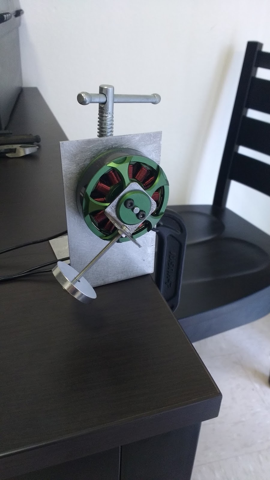
     Of these suggestions, we deemed that motors might be the most practical to use. The following sketch shows an early idea of how they might be implemented in conjunction with the current design.

A sketch of the leg showing a motor being used to move the leg.
     We also found some research articles that suggested that either a large load could be applied less frequently, or a smaller load could be applied more frequently in order to maintain healthy bone. The amount of strain needed to be applied and the frequency will determine the type of motor(s) we purchase, should we choose to go that route, but we need to find and finalize the modulus of elasticity first.
      The following papers were found when researching this topic:

"The Longitudinal Young’s Modulus of Cortical Bone in the Midshaft of Human Femur and its Correlation with CT Scanning Data"

Abstract: This study was concerned with establishing the regional variations in the magnitude of the longitudinal Young’s modulus of the cortical bone in the femoral midshaft and with investigating whether a relationship existed between the Young’s modulus of bone and the CT number. Were such a relationship to exist this would provide a noninvasive method of assessing the quality of bone in the regions of fixation of implants to bone. The data would be of considerable aid to designers of implant stems to withstand the stresses arising at its interface with the bone. Five pairs of fresh frozen human femora were used. Several beam-shaped small specimens were methodically harvested from each pair and were used to measure the longitudinal modulus adopting the three-point bending test, which was carried out with a specially constructed and validated apparatus. CT scans of the bone were obtained, prior to harvesting the specimens, and the CT number was measured at locations corresponding with the specimen sites. The results indicate that in the femoral midshaft the cortical bone has an average Young’s modulus value of 18600 ± 1900 MPa. This agrees well with data obtained by other researchers using different experimental methods. Statistical analyses revealed no regional variations in the value of the longitudinal modulus of the bone. No correlation was found between the bone modulus and the CT number. Thus a noninvasive method for establishing the bone properties still remains a challenge.
Link: http://link.springer.com/article/10.1007/s00223-002-2123-1

"Elastic modulus and hardness of cortical and trabecular bone lamellae measured by nanoindentation in the human femur"

Abstract: "The mechanical properties of bone tissue are determined by composition as well as structural, microstructural and nanostructural organization. The aim of this study was to quantify the elastic properties of bone at the lamellar level and compare these properties among osteonal, interstitial and trabecular microstructures from the diaphysis and the neck of the human femur. A nanoindentation technique with a custom irrigation system was used for simultaneously measuring force and displacement of a diamond tip pressed 500 nm into the moist bone tissue. An isotropic elastic modulus was calculated from the unloading curve with an assumed Poisson ratio of 0.3, while hardness was defined as the maximal force divided by the corresponding contact area. The elastic moduli ranged from 6.9±4.3 GPa in trabecular tissue from the femoral neck of a 74 yr old female up to 25.0±4.3 GPa in interstitial tissue from the diaphyseal cortex of a 69 yr old female. The mean elastic modulus was found to be significantly influenced by the type of lamella (p<10−6) and by donor (p<10−6). The interaction between the type of lamella and the donor was also highly significant (p<10−6). Hardness followed a similar distribution as elastic modulus among types of lamellae and donor, but with lower statistical contrast. It is concluded that the nanostructure of bone tissue must differ substantially among lamellar types, anatomical sites and individuals and suggests that tissue heterogeneity is of potential importance in bone fragility and adaptation."
Link: http://www.sciencedirect.com/science/article/pii/S0021929099001116

"The elastic properties of trabecular and cortical bone tissues are similar: results from two microscopic measurement techniques"

Abstract: "Acoustic microscopy (30–60 μm resolution) and nanoindentation (1–5 μm resolution) are techniques that can be used to evaluate the elastic properties of human bone at a microstructural level. The goals of the current study were (1) to measure and compare the Young’s moduli of trabecular and cortical bone tissues from a common human donor, and (2) to compare the Young’s moduli of bone tissue measured using acoustic microscopy to those measured using nanoindentation. The Young’s modulus of cortical bone in the longitudinal direction was about 40% greater than (p<0.01) the Young’s modulus in the transverse direction. The Young’s modulus of trabecular bone tissue was slightly higher than the transverse Young’s modulus of cortical bone, but substantially lower than the longitudinal Young’s modulus of cortical bone. These findings were consistent for both measurement methods and suggest that elasticity of trabecular tissue is within the range of that of cortical bone tissue. The calculation of Young’s modulus using nanoindentation assumes that the material is elastically isotropic. The current results, i.e., the average anisotropy ratio (Full-size image (<1 K)) for cortical bone determined by nanoindentation was similar to that determined by the acoustic microscope, suggest that this assumption does not limit nanoindentation as a technique for measurement of Young’s modulus in anisotropic bone."
Link: http://www.sciencedirect.com/science/article/pii/S0021929098001778

"THE MATERIAL PROPERTIES OF HUMAN TIBIA CORTICAL BONE IN TENSION AND COMPRESSION: IMPLACATIONS FOR THE TIBIA INDEX"

Abstract: "The risk of sustaining tibia fractures as a result of a frontal crash is commonly assessed by applying measurements taken from anthropometric test devices to the Tibia Index. The Tibia Index is an injury tolerance criterion for combined bending and axial loading experienced at the midshaft of the leg. However, the failure properties of human tibia compact bone have only been determined under static loading. Therefore, the purpose of this study was to develop the tensile and compressive material properties for human tibia cortical bone coupons when subjected to three loading rates: static, quasistatic, and dynamic. This study presents machined cortical bone coupon tests from 6 loading configurations using four male fresh frozen human tibias. A servo-hydraulic Material Testing System (MTS) was used to apply tension and compression loads to failure at approximately 0.05 s-1, 0.5 s-1, and 5.0 s-1 to cortical bone coupons oriented along the long axis of the tibia. Although minor, axial tension specimens showed a decrease in the failure strain and an increase the modulus with increasing strain rate. There were no significant trends found for axial compression samples, with respect to the modulus or failure strain. Although the results showed that the average failure stress increased with increasing loading rate for axial tension and compression, the differences were not found to be significant. The average failure stress for the static, quasi-static, and dynamic tests were 150.6 MPa, 159.8 MPa, and 192.3 MPa for axial tension specimens and 177.2 MPa, 208.9 MPa, and 214.1 MPa for axial compression specimens. When the results of the current study are considered in conjunction with the previous work the average compressive strength to tensile strength ratio was found to range from 1.08 to 1.36."
Link: http://www-nrd.nhtsa.dot.gov/pdf/esv/esv20/07-0470-O.pdf

     This week team members also updated their ethics papers as the final draft is due at the beginning of Week 10.

Monday, November 7, 2016

Week 8

     This week during class, we discussed some of the articles we had researched the previous week. We would like to look into the bone's response to mechanical stimuli more, and see if there is a minimum threshold required to prevent bone loss. We also got the thumbs-up for using the Instron tensile test machine, so we ran some tests on our elastic bands.
     The elastic bands were cut into strips that were 10 cm long and 1.5 cm wide. Each elastic band (there are five different ones) was cut up to provide three samples for testing. Shown below are pictures of this process.
Shown are the small elastic band strips used for tensile testing.
The Instron machine pulling one of the black elastic band samples.
Testing the different elastic bands.
     Isaac later compiled the data gathered from the tests and organized them into an excel file. Shown below are plots generated for each different color band.
This is an example of one of the results from a black elastic band.
Black elastic band results.

Blue elastic band results.

Green elastic band results.

Red elastic band results.

Yellow elastic band results.

      During the week, we met as a group to delegate duties and discuss Deliverable 5. We started on some Solidworks, updated the excel mathematical model, and constructed the critical module test using elastic bands.
Version 1 of the harness drawn in Solidworks.
Version 1 of the ankle brace drawn in Solidworks.

 The critical module test utilized several different bands in order to provide sufficient load. We tried to make the elastic band module as similar to the spring model as possible (in regards of things like anchor point locations and force) so that fair testing and comparison between the two methods would be possible.
This was for the inside of the arm. It contains two black bands and one blue band, all stacked on top of each other.

This is the outside of the arm. Bands were attached to the wooden model via duct tape.
The final product.

Example of the math model for the constant force spring system.
Moment about the inside of the arm using the spring system.
Moment about the outside of the arm using the spring system.
Using both the inside and outside spring system.
Moment about the inside of the arm using elastic bands.

Moment about the outside of the arm using elastic bands.

Using both the inside and outside elastic band system.
     Our team had some questions about the architectural design portion of the Deliverable, so we emailed/met with our professor. Dr. Gordon said that he was surprised we hasn't asked for an extension on the deliverable, and told us that he would prefer we wait to submit the deliverable and focus on doing more research. The research should concentrate on whether there is a minimum force needed to stimulate the bones and should also provide alternative/additional options for targeting the astronauts' legs. (This had always been a point of concern, and Jake had emailed a former professor and astronaut who confirmed that astronauts do not use their legs extensively while in zero gravity).