This is the first week of class since Christmas break. Over break, we ordered parts for our project, which were waiting when school resumed. Below is a picture of the items we ordered.
 |
| The items ordered over Christmas break. |
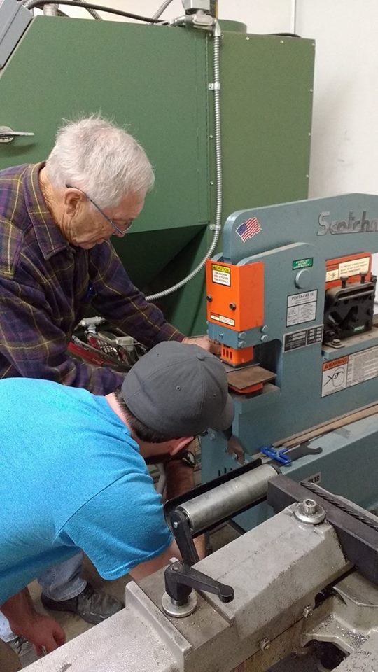
We double checked that we received all of the items, and then started constructing the base plate in order to test the motor. We went to Wes' shop and got his help to do this. We bent a sheet of aluminum to create a 90-degree bend, and also punched holes into the metal in order to anchor the motor to the plate.
 |
| The above pictures show our team fabricating the test bracket in the lab. |
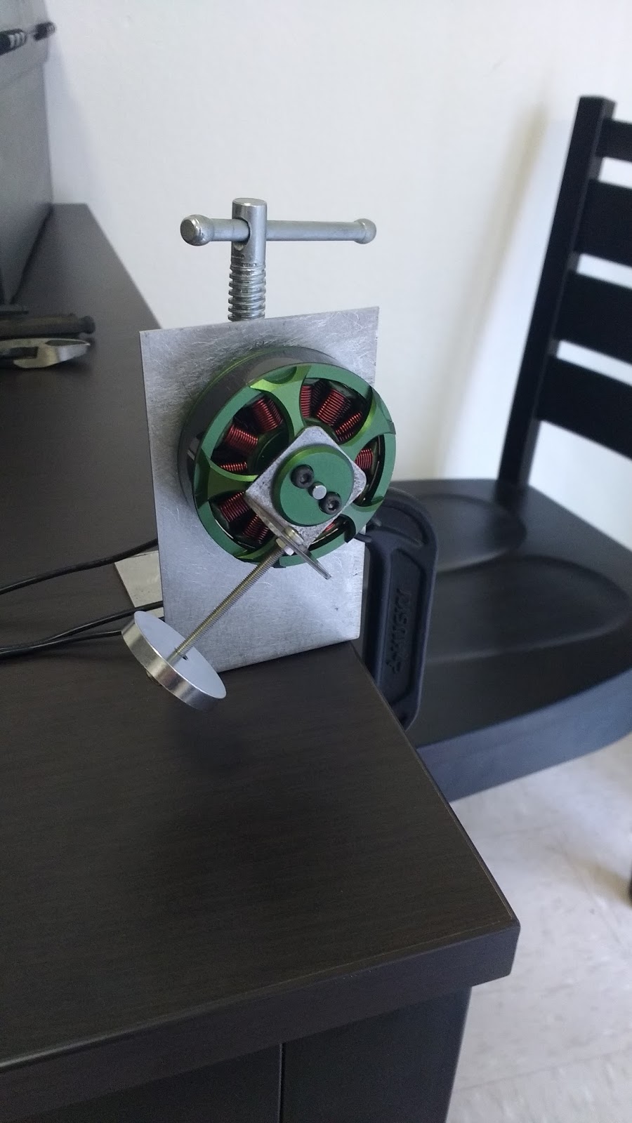
Once the test bracket was constructed, we began our motor testing. We started out by using a 50 mm screw and spinning it by itself at different speeds (increased incrementally). We then added a small mass and repeated the process, and slowly worked up to larger masses. The mass sets were threaded onto the screw via the hole in their centers. We used the tachometer to measure the RPM of each different combination. The motor was spun via an Arduino and motor controller (as shown on the order form), with much of the code being found/written by Max.
 |
| This shows the set-up with one of the smaller masses being attached to the motor. |
 |
| The motor test bracket as shown from the back (held down by a clamp). |
 |
| Using the tachometer to measure the RPM of the spinning mass. |
 |
| Max used Arduino code and a motor controller to control the motor's speed. |
The results from the testing can be seen in the picture below:
 |
| The "scary" sections were when the motor hit a harmonic and vibrated in a scary-fashion, which didn't allow for proper readings. |
We also met up to discuss our options for mounting the mass to the motor, as well as the motor system to the ankle. During our testing, we had found that the head of the 50 mm screw sheared off, launching the mass into the air. Obviously we do not want this, so we explored several alternative options for attaching the weights to the motor safely. Some ideas were using a bigger screw, welding a screw/rod to the motor, redoing the bracket to change the resonant frequencies, using a bike cable rather than screw, and machining out a solid piece that would serve as both the mass and the "arm." We felt that the last two ideas were the best, but we think that there will be difficulties with both options. Therefore, we are hoping to discuss them with our tech adviser and/or Wes before purchasing anything.
 |
| Ideas of how to attach the mass and motor configuration together. |
For attaching the motor to the ankle/leg, we want something that is cost-effective (re: not expensive), but that also provides stability. Our current ankle brace would not be sufficient on its own as it would allow a lot of room for movement once the motor started spinning. Ideas we contemplated were 3D printing "shin guards" and then Velcro cinching them down, buying a sturdy boot (such as a ski boot or work boot), or purchasing a sturdier ankle brace. We believe we will try to 3D print material, as this would not count against our budget. However, we would again like to consult with both the tech adviser and Josh Park before making a decision.
 |
| Ideas of how to attach the motor configuration to the ankle. |


