Monday, October 31, 2016

Week 7

     This week we spoke with Dr. Gordon about our project budget. He said that our budget would likely be around $500-600. We also further defined what we could use for anchor points and guide loops. We decided that a fully-body harness would be essential to our project, as we think that this would make an excellent (and comfortable) place to anchor our bands and/or springs. We decided that (if budget permits) using braces might be a good option for further anchor points since they are already designed for specific body parts and are made to be comfortable for long periods of wear. An additional benefit of using braces is that many braces have Velcro fasteners, meaning that they can be put on and taken off quickly and easily. Any sort of "guide loop" could then be mounted to these surfaces. We would ideally like two knee braces, two ankle braces, two elbow braces, and a pair of gloves. (This would allow us to reach the more distal portions of the body.)
Below is an example of what we are hoping to use.
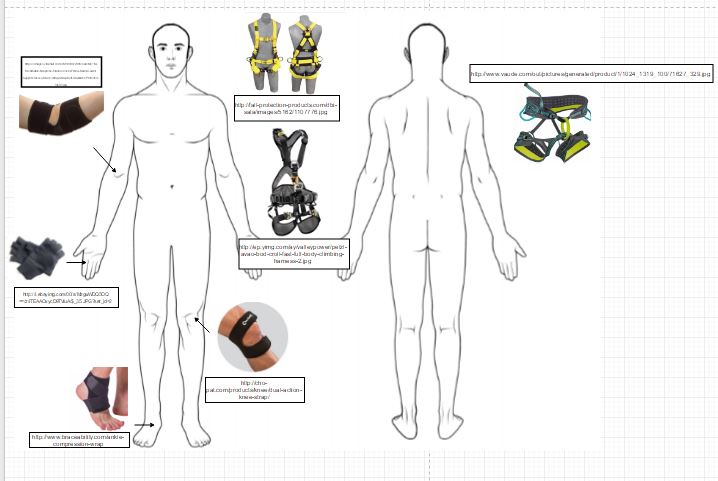
This diagram shows the different braces we are looking into using, as well as the harnesses we are considering. If  budget permits, we would like one the body harnesses shown, rather than the standard climbing harness on the right (which lacks the upper body section). 
Brainstorming on budgets and attachments. 
     In addition, Isaac started working on a CAD model that will be submitted with our Deliverable 5 (due Monday of Week 8). This will include a simple "person" and will show where the device is located on the body and the different attachment points. This will need further developing.
Isaac using Solidworks to create a CAD model for our project.
     Finally, we were hoping to use the tensile testing machine to get pull profiles for our elastic bands, as this is necessary prior to performing the shakedown testing. However, this was delayed another week as necessary paperwork needed to be filed and approved in order to receive training on the device. However, Dr. Gordon informed our group that since our project won't be able to be truly tested, it is more research-intensive than some other groups. He pushed our due date for Deliverable 5 back one week (to Week 8), which allowed us to concentrate on research rather than testing and building. This research will continue until Thanksgiving, but below is a summary of some of the research performed this week:

"The influence of static and dynamic loading on marginal bone reactions around osseointegrated implants: an animal experimental study."
Link: http://onlinelibrary.wiley.com/doi/10.1034/j.1600-0501.2001.012003207.x/full  

Although the bone-implant contact was not significantly different for the dynamically loaded versus the statically loaded and control implants, bone loss was observed at a close distance from the implants when they were loaded dynamically. This supports the hypothesis that excessive load can indeed trigger bone resorption through the induction of micro-damage in the bone.

"Mechanical Signaling for Bone Modeling and Remodeling"
Link: https://www.ncbi.nlm.nih.gov/pmc/articles/PMC3743123/pdf/nihms-281049.pdf

"Loading results in adaptive changes in bone that strengthen bone structure. Bone's adaptive response is regulated by mechanotransuction. We found that applying loading to the forelimbs of rats improved bone strength by 64%. Interestingly, the improvement in bone mineral content (BMC) in these rats was only a modest 7%. Consequently, mechanical loading adds mass but also causes the cross-sectional shape of long bones to become more structurally efficient." In adults (after growth has been cmpleted, "the effects of exercise shift from bone building to prevention of bone loss. In the adult skeleton, exercise reduces bone turnover by reducing bone resorption. Our studies employ a machine that applies axial loads to the forelimbs of rats or mice. In the rat ulna, where bone growth is directed to regions of high strain energy, improvement in function is dramatically improved. After 16 weeks of loading, the rat ulna will sustain 100-fold more loading cycles before failure." The article also includes information on the signaling pathways and specific cellular components/proteins that may cause bone growth. "Studying the effect of mechanical stimulation on resorption in animal models has been much more difficult than studying the effects on formation, and consequently, our understanding of the mechanisms involved is less developed. Part of the problem is that most of the animal models developed for studying the effects of increased loading on the skeleton are designed for addressing cortical bone in rodents. Because rodent cortical bone does not undergo Haversian remodeling, resorption data are scarce." It also says that bones may become desensitived to mechanical loading and produce less osteogenic activity. < This needs to be looked into more!!

"A threshold of mechanical strain intensity for the direct activation of osteoblast function exists in a murine maxilla loading model"
Link: https://goo.gl/S00H2u

"The purpose of this study is to clarify precisely what intensity level of mechanical strain is necessary to accelerate bone formation. The mice in the loaded group were subjected to continuous loading with 191kPa using the appropriate weight ingot for 30min/day on seven consecutive days." They tested for inflammation/swelling that resulted from the loading at two different locations: one close to the loading side and one farther away. They found that osteoclast number increased in both regions, but was much higher at the closer location. 


"Bone Formation"

"As new bone material is added peripherally from the internal surface of the periosteum, there is a hollowing out of the internal region to form the bone marrow cavity. This destruction of bone tissue is due to osteoclasts, multinucleated cells that enter the bone through the blood vessels (Kahn and Simmons 1975Manolagas and Jilka 1995). Osteoclasts are probably derived from the same precursors as macrophage blood cells, and they dissolve both the inorganic and the protein portions of the bone matrix (Ash et al. 1980Blair et al. 1986). Each osteoclast extends numerous cellular processes into the matrix and pumps out hydrogen ions onto the surrounding material, thereby acidifying and solubilizing it (Figure 14.17Baron et al. 19851986). The blood vessels also import the blood-forming cells that will reside in the marrow for the duration of the organism's life. The number and activity of osteoclasts must be tightly regulated. If there are too many active osteoclasts, too much bone will be dissolved, and osteoporosis will result. Conversely, if not enough osteoblasts are produced, the bones are not hollowed out for the marrow, and osteopetrosis results (Tondravi et al. 1997)."

"Benefits for Bone From Resistance Exercise and Nutrition in Long-Duration Spaceflight: Evidence From Biochemistry and Densitometry"


“These data document that resistance exercise, coupled with adequate energy intake (shown by maintenance of body mass determined by dual-energy X-ray absorptiometry [DXA]) and vitamin D, can maintain bone in most regions during 4- to 6-month missions in microgravity. This is the first evidence that improving nutrition and resistance exercise during spaceflight can attenuate the expected BMD deficits previously observed after prolonged missions.  2012 American Society for Bone and Mineral Research. It is well recognized by researchers in exercise physiology and bone biomechanics that bone needs to be optimally overloaded to have a stimulatory effect, which cannot always be provided by aerobic exercises."

"Rodent Research Contributes to Osteoporosis Treatments"

“We know that sclerostin production in bone is regulated by mechanical loading, but what we didn’t know was if you completely unloaded the skeleton’s bone formation pathway, which is essentially what happens in microgravity, whether our molecule that blocks sclerostin would still result in increased bone formation and bone strength. “If you take a human or an animal and put them in microgravity, they will lose muscle and bone at rates that are incredibly fast, much faster than a patient on Earth suffering from osteoporosis. They’ll lose bone at a rate 10 times faster in space than that individual. “For instance, static strains do not engender adaptive responses [8,9] whereas dynamic strains which change at high physiologic rates (as in impact loading) engender greater adaptive responses than those which change more slowly [10–13]. The on/off points therefore relate
to a strain-related stimulus rather than a particular strain value [9]."

Pharmaceuticals Solutions; "Mice Studies in Space Offer Clues on Bone Loss"
Link: http://www.nasa.gov/offices/oct/feature/mice-studies-in-space-offer-clues-on-bone-loss/

“One experiment focused on sclerostin, a naturally secreted protein that tells the body to dial down the formation of new bone. The mice were injected with an antibody that blocks sclerostin, essentially telling the body to “let up on the brake,” explains Chris Paszty, Amgen’s research lead on the project. That allowed the rodent bodies to keep regenerating bone tissue, resulting in increased mineral density and improved bone structure and strength. The results were encouraging: the mice injected with the antibody showed increased bone formation and improved bone structure and bone strength, similar to what was seen in the mice who remained on Earth.”

"Animal Experimental Measures of Functional Strain and Adaptation in Bone"
Source: Mechanical Strain and Bone Cell Function: A Review
P. J. Ehrlich and L. E. Lanyon
Department of Veterinary Basic Sciences, The Royal Veterinary College, London, UK

"These human exercise studies also support the data from animal studies that local loading induces local site specific changes in bone architecture [15–17]. Regardless of whether tensile or compressive forces were applied, the bone responded to intermittent, but not static loading. The first study to combine these approaches was that of O’Connor et al. [10] who used a pneumatic actuator to apply bending loads to sheep radii through metaphyseal pins. This study demonstrated a significant correlation between maximum strain rate and the degree of bone hypertrophy. This inference has been confirmed by a number of subsequent studies [11,19,32]."


Monday, October 24, 2016

Week 6

     This week was midterm week for many of our other classes, so we chose to work on things individually and did not meet together very often as a group. On Monday we presented our mid-semester presentation and then watched and reviewed the other five groups. This session was treated like a "design review" and allowed feedback from other groups on the planned designs. The mid-semester packet containing Deliverables 1-4 and a second peer evaluation were also due.
     We met as a group on Tuesday night and clarified what our next steps will be. Before we can finalize what method we will use and create detailed designs, we need to complete our shakedown tests. We emailed the tech adviser to see when Bourns Lab was open, as we wanted to get pull profiles on the elastic bands that we bought (the force for each is not specified). Once this was done, we could finish constructing our shakedown model, test the two and compare the results, and then move forward.
Our elastic bands are only categorized as ambiguous things, like "extra heavy" or "medium."

     Our adviser let us know what days the lab was open and two team members went to try to use the tensile testing machine (Isaac and Max). However, they found out upon arriving that specific paperwork is needed to operate the machines, and as such, they were not permitted to continue. Because of this, our shakedown testing has been delayed another week and we hope to use the machine during class time with our professor present.
Our team was not permitted to use the machines in Bourns Lab.
     A mathematical "model" was also constructed this week. It was created in Excel and models the shakedown devices we created (or is roughly the size of an arm). This includes different angles, forces, positions, and moments. The preliminary results can be seen below.

     Finally, we researched the topic further and also each worked on our ethical paper assignment (the draft). This included choosing an engineering failure pertinent to our field of study, analyzing why the failure occurred, identifying ethical issues, and then getting someone else from the class to peer review and edit the paper before submission.

Monday, October 17, 2016

Week 5

     This week we received the items we ordered for our shakedown testing (our constant force springs and elastic bands). We decided to go to the engineering lab and start constructing the wooden "arm" described in the Week 4 blog post. As we are not technically certified to work on our own in the lab yet, we had Wes help us.

The wooden boards modeling the upper and lower arm were cut to be roughly the same length as Isaac's arm. 
Wes helped us construct the model.
A hinge was used to connect the two boards. Small holes were cut out so that the hinge was in the center of the boards, rather than sticking out. This mimics a natural elbow joint.  
We also drilled holes on the top of the boards at 2 cm intervals. Currently we are using eye hooks to guide the string and act as anchor points, and the different holes allow the placement of the anchor points to be adjusted. 

Wooden boards connected by a hinge.

This picture shows the holes drilled in the two boards.
Once the "arm" was built, we attached the spring system. Our constant-force spring was housed in a 3D printed casing, and the end of the spring could be pulled out (similar to the way that tape measures can be used). One issue we found is that the spring can recoil on itself and then not return to the casing. This issue seemed to be mostly resolved when we attached the spring to the board, but bears further testing, as this may be a potential issue that causes us to move away from the design altogether.

Example of the spring recoiling and getting jammed. 
The spring system was composed of two springs, acting opposite each other (such as two opposing muscles). In other word, as one spring was "contracting," the other one was lengthening. Parachute cord (or paracord) was tied to the end of each spring and threaded through the guide holes until they were anchored. As stated before, screw eye holes were used to provide the guide holes and anchor points. The spring casings were taped to the end of the "upper arm" board, as their placement on the actual body would likely be near the shoulders.

Constructing the model.

The final model of the spring system.
We finished building the model for the spring system. Rather than having to deconstruct the system whenever we wanted to test elastic bands, we constructed a second "arm." We did not yet attach the elastic bands, as we are considering testing their pull profiles first, but we will do so next week.
     Next week, we will use the force transducer to test the moment generated about the elbow joint for both models. We will also test how changing the anchor points affects the moment and attempt to find  comfortable (natural) neutral points for the user.

Materials to be used for shakedown testing.
    The rest of the week, we worked on the mid-semester presentation and packet that are due on Monday. These are essentially summaries of our problem, what we have done to this point, and our future designs.

This is our presentation cover slide. 

Monday, October 10, 2016

Week 4

     At the end of last week, we had created decision matrices and had narrowed down our concept options. This week, we discussed the advantages of using either a spring system or elastic band system as the primary means of resistance with our project Tech Advisor (Dr. Gordon). This was also determined to be the critical module, because the failure of one of these mechanisms would render the entire device essentially useless.
     As neither one had a clear advantage over the other, it was decided that both would be tested in a shakedown test. We drafted plans to create a very simple two-board system that would represent the upper arm, forearm, and elbow joint. We are planning on attaching constant force springs and strings to the arm, and testing the moment generated using a force transducer. We will do the same thing with elastic bands, and then compare the two results. 
Critical module testing. This picture shows the two boards representing the arm and the spring system that would be used. 
This shows the test using elastic bands. 
Additionally, Isaac Need designed a spring casing in Solidworks which will be 3D printed. This will hold the constant force spring and keep it from moving. 

     The following shows some of our ideas from brainstorming modules. 

Module categories.
The items in red are examples of module brainstorming.
     We felt that we could not move forward with further detailed designs on specific modules until after we perform the shakedown tests and decide which method we will utilize (all of the modules depend on our method).

     We ordered parts for our shakedown tests, which should be arriving at the beginning of Week 5. We will then construct the test described above, and move forward with our designs. 

Monday, October 3, 2016

Week 3

This week we clarified our understanding of the difference between strategies and concepts, and finished off brainstorming different strategies for our project. We ended up with ~30 ideas for strategies, and then chose the top three ideas and brainstormed the pros and cons of those strategies. The top three strategies were tension, compression, and resistance.
Strategies List

Once we had selected our strategies, we brainstormed concepts for each of those strategies. (We had already inadvertently brainstormed several concepts last week.) Once again, we were asked to select the top 3 concepts per strategy (so 9 concepts total), and consider the pros and cons of each. To do this, each team member rated the concepts individually. We then discussed our ratings as a group and argued for why or why not a concept should be considered. Shown below is an example of how this process was completed.
Example of concept ideas for Resistance strategy.

Excerpt from choosing a concept within the Resistance strategy. The thee concepts on the right were chosen as the winners.

The following pictures show examples of the 9 concepts that were selected.
Magnetic joints
Velcro suit

Velcro suit
Tight-fit joints
Elastic bands/Elastic fabric

Compression circular tubing
Pulley system
Elastic fabric

Once we had our 9 concepts, we put them into two decision matrices: one for long-term use and one for short-term use. (Previously in our project we defined "short-term" to be anywhere between 30 minutes-1 hour and "long-term" to be 3 hours or longer.) The categories for the matrices were identical, but the weights given to each category were different. For example, we decided that comfort was of lower priority for short-term use than for long-term use.
We rated each category on a scale of 1-5, with 5 being the best and 1 being the worst.
Long duration decision matrix

Short duration decision matrix

Based on both decision matrices, we were able to rule out five ideas automatically. The remaining four were somewhat close in score, and, due to the nature of our project, may eventually be incorporated. (We believe it would be both beneficial and feasible to incorporate multiple concepts as some might be more effective on different parts of the body.)
The elastic bands scored the highest in both decision matrices, and will thus be chosen as our single concept that we will generate modules for (starting next week).